16 December 2024
INPOWEL: EMT models for grid forming assets
Developing EMT and RTDS models for BESS and E-STATCOM in GFL and GFM modes of operation.
Context
Grid stability challenges in the transition to 100% renewables
To ensure grid stability amid the transition to 100% renewables and achieve carbon neutrality by 2050, it is essential not only to expand renewable energy sources but also to maintain grid stability. The integration of renewables is known to reduce system inertia necessary for frequency contingencies, limiting the ability to counteract frequency or a large Rate of Change of Frequency (RoCoF) events. It also reduces the short circuit level (SCL) for handling voltage issues during faults because renewables can't inject high currents quickly, and also can make renewables more unstable because their voltage is more sensitive to changes in current. This has been evidenced by various real-world instances of unit disconnections and oscillatory behaviour. Different Transmission System Operators (TSOs) are addressing these new stability challenges through initiatives like Germany's System Stability Roadmap and the UK's National Grid Stability Pathfinder program.
Historically, Europe's power system inertia reduced by 20% on average between 1996 and 2016 and is projected to decrease by an additional 20-30% by 2030. Synchronous generators contribute significantly to fault current during short circuits, providing 5-7 times their rated armature current, whereas inverter-based resources offer much lower fault current due to limited overload handling capability, contributing only 1.2-1.5 times the inverter steady-state current rating.
Currently, synchronous condensers (SCs) often combined with flywheels are the preferred solution to provide both inertia and SCL. However, they come with high costs, significant operational expenses, and require substantial physical space, making them impractical for accommodating high renewable penetration. Thus, there is a pressing need for more efficient technological solutions to address these stability challenges.
Grid-Forming Converters: A solution for future grids
According to projections from the IEA, IRENA, and BloombergNEF, global installed renewable energy capacity is expected to triple by 2030 and then triple again from 2030 to 2050, resulting in nearly a tenfold increase from current levels. Solar PV and wind are projected to make up 70% to 90% of these additions. All these renewable sources are integrated into the grid using power electronic-based converters.
Controlling these converters to mimic the stabilizing properties of conventional synchronous generators (SGs) would provide significant benefits. This is the purpose of grid-forming (GFM) converters. Unlike traditional grid-following (GFL) converters, which need a strong grid for synchronization via a phase-locked loop (PLL), GFM converters can independently “form” the grid, operating robustly even in weak grid conditions.
Grid-following converters perform well when the presence of GFL inverter-based resources (IBRs) is relatively low. However, as IBR levels exceed 60% to 70% of instantaneous generation, maintaining grid stability becomes increasingly challenging. Additionally, the growing share of IBRs can lead to oscillations and interactions within the network.
Advanced simulations and model validation for stability studies
Traditional Root Mean Square (RMS) simulations use a time step of 10 milliseconds (ms) and can effectively capture frequencies up to around 50 Hz. However, they can't capture faster transients and dynamics. On the other hand, ElectroMagnetic Transient (EMT) simulations use much shorter time steps, typically between 1 to 50 microseconds (μs), allowing them to capture high-frequency phenomena and fast transients in power electronic-based IBRs. For example, transient switching frequencies of 2-3 kHz can be accurately modeled with time steps of 30-50 μs. For EMT simulations involving frequency content up to 10 kHz, time steps of about 10 μs are typically needed.
To study IBR interactions and develop suitable performance requirements for the future grid, it's important to create generic EMT models for technologies like grid-forming inverters. However, it's crucial to validate these models to ensure they are suitable for the studies. It's equally important to understand the limitations of these generic models and their applicability.
As part of the INPOWEL project, generic EMT and Real-Time Digital Simulator (RTDS) models for Battery Energy Storage Systems (BESS) and Static Synchronous Compensators with Energy Storage (E-STATCOM) have been developed. These models represent the behavior of these systems in both grid-following and grid-forming modes. The models are modular, meaning the same model can represent different technologies based on user input.
Extensive validation of the models has been conducted by comparing their performance against blackbox models from original equipment manufacturers (OEMs). The validation was carried out under various system strength scenarios, voltage, frequency, and phase angle changes, and balanced/unbalanced faults. This validation helps identify the potential limitations of using generic models.
The study also includes an application in a larger network where grid-following converters showed oscillations, and grid-forming technology helped control these oscillations. Static evaluation metrics were used to identify the best locations and ratings for grid-forming devices.
The goal of these simulation studies is to identify interactions between various technologies and the grid, as well as to recognize any limitations of EMT models and propose best practices for using them.
EMT modeling details
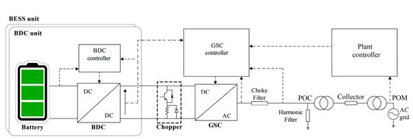
A unified EMT model has been created in PSCAD for both BESS and E-STATCOM. This model supports both GFM and GFL modes of operation through a user‐defined control setting. Figure 1 illustrates a simplified schematic diagram of the model which uses an aggregated plant model with a two‐stage topology.
Comparison of generic EMT model performance with a blackbox model
Using a single source infinite bus test system (shown in Fig. 2), we compared the performance of GFM and GFL assets against blackbox models from original equipment manufacturers (OEMs) under different conditions.
The tests checked how the models performed in various scenarios, including:
- Different short circuit ratio (SCR) levels and X/R (Reactance to Resistance) ratios
- Changes in frequency, voltage, and phase angle
- Balanced and unbalanced faults
These tests were done when the IBR device was operating well within its current limits and also when it was close to hitting those limits. It's expected that the device might reach its current limits due to a disturbance or might already be operating at those limits before an event occurs.
Figure 2. Single source infinite bus (SSIB) setup for a collection of identification tests
Over 130 tests were conducted to show how the system performs, identify its limitations, and understand its sensitivity under different conditions and faults. The following comparisons were made:
- The generic PSCAD model was compared with the vendor's blackbox PSCAD model.
- The generic PSCAD model was compared with the generic real-time simulator model.
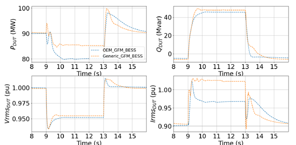
For example, in the test system shown in Figure 2, when operating in GFM mode, close to maximum power output (0.9pu), and with a high SCR of 10.0 and X/R ratio of 10.0, the performance for step changes in infinite bus voltage magnitude is compared in Figure 3. The response is observed at the point of interconnection (high voltage side of the interconnection transformer).
The reactive power response between the generic model and the OEM model shows a good match. However, there are differences in the steady-state value of active power response and the magnitude of the current response. This difference could be due to how the OEM’s model handles power limits.
At this operating point, the models are close to their power and current limits. When the voltage drops, the reactive power increases to support the voltage. But, with the pre-disturbance level of active power, this increase in reactive power can exceed the inverter's limits. As a result, the OEM model reduces its active power output.
The generic model also reduces its active power output in this scenario, but not as much as the OEM model. This leads to a difference in current magnitude. Such differences are expected near the operational limits of these devices when comparing a generic model with an OEM model. OEMs often have proprietary methods (Intellectual Property) to handle limits and ensure smooth recovery, which may not be fully captured by generic models.
Despite these differences, the performance of the generic model is considered suitable and acceptable for its intended use.
Figure 3. Comparison of performance of BESS in GFM mode for step change in
voltage at an SCR of 10 and at active power of 0.9pu
As George Box famously said in 1976, “All models are wrong, some are useful.” This reminds us that generic models will always need improvement because they are not designed to exactly match the characteristics of an OEM model. Instead, generic models are meant to show the general behavior of a technology. Therefore, continuing validation and testing are often necessary to make sure they are accurate and reliable.
Conclusions
- Generic models might struggle when operating near their limits because original equipment manufacturers often use proprietary methods (Intellectual Property) to handle these situations.
- Static evaluation metrics can be used for initial studies to identify where potential instabilities may occur. These metrics also help identify where grid forming devices can be placed and to what extend that could help the network.
- Real-time simulation lets you interact with a simulation model live, creating a digital twin—a live digital copy of the power system that is continuously updated with real-time measurements.
Next steps
- Extension of the models to include additional sources of energy such as wind, PV, and/or HVDC
- Improvement in current limiting logic and coming out of current limits after an event
- Improvement in ride through behavior during an unbalanced fault.
Partners
  |


